- All
- Product Name
- Product Keyword
- Product Model
- Product Summary
- Product Description
- Multi Field Search


Views: 0 Author: Site Editor Publish Time: 2026-11-10 Origin: Site


Introduction
Even the most sophisticated manufacturing equipment is only as capable as the digital instructions guiding its movements. Have you ever watched an expensive sheet of metal get ruined because of a simple parameter error? It happens more often than you might think on the shop floor. Many beginners and seasoned industry professionals alike frequently grapple with digital compatibility hurdles. They face incorrect parameter configurations or sheer confusion when navigating between design and control programs. Ultimately, these bottlenecks lead to wasted materials, inflated production times, and subpar edge quality.
This comprehensive guide serves as an objective, deep-dive resource for understanding, selecting, and mastering your digital ecosystem. Whether you are operating a compact desktop engraver or a heavy-duty industrial system, selecting the correct Laser Cutting Software is the critical first step to operational success. Integrating the right digital architecture with your hardware is simply non-negotiable for achieving precise, repeatable results.
Key Takeaways
The Three Pillars: Successful processing relies on three distinct digital tools. You need CAD for geometric design, CAM for translating designs into machine-readable code, and Control Software for executing the code and running the physical machine.
Vector vs. Engineering: 2D vector applications, such as Adobe Illustrator, are optimal for flat, artistic geometries. In contrast, engineering platforms like AutoCAD or Fusion 360 are mandatory for precise, mechanical tolerances.
Machine Specificity: Industrial equipment requires specialized programs. A high-power system relies on robust software like CypCut to manage complex metal cutting parameters and advanced material nesting.
Tube Cutting Complexity: Operating rotary equipment demands advanced 3D processing capabilities to handle continuous axis calculations and intersecting tubular geometries.
Crucial Features: Standardize your software search around essential functions like kerf compensation, auto-nesting algorithms, and broad file format compatibility.
Demystifying the digital workflow is essential for efficient production. The process of turning a concept into a physical part involves a specific sequence of software applications. Each serves a distinct purpose in the manufacturing pipeline. Skipping or misunderstanding a step is exactly where most fabrication errors occur.
Computer-Aided Design is the foundational environment where the geometric creation process occurs. Operators use these platforms to draw precise shapes, define exact dimensions, and input text. For laser applications, relying on vector graphics rather than pixelated raster images is crucial. Imagine trying to cut a crisp acrylic logo using a blurry JPEG. The machine simply would not know where the true boundary lies. Vector lines provide the exact, infinitely scalable coordinates the cutting head needs to follow. This ensures clean, continuous paths.
Once the design is finalized, Computer-Aided Manufacturing software takes over. Its primary function is to translate the geometry into G-code, which is the numerical control language the hardware understands. Within this environment, operators define critical material parameters. Specifically, this includes setting the cutting speed, power percentages, pulse frequency, and the required number of passes. Getting this right cleanly severs the material without causing an excessive heat-affected zone.
Control software provides the graphical user interface connected directly to the motherboard. It executes the generated code, allows the operator to jog the head manually, and frames the physical workspace. This ensures the raw sheet is positioned correctly before the beam ever fires. Furthermore, modern industrial environments frequently combine these functions into a single, cohesive package for streamlined operation.
Selecting the appropriate design tool depends entirely on your production goals. The industry typically divides these tools into artistic vector applications and mechanical engineering platforms.
For projects prioritizing aesthetics, typography, and organic shapes, graphic design software is highly effective.
Adobe Illustrator: Recognized as the industry standard for graphic designers, Illustrator excels at generating intricate patterns. It offers robust pathfinding tools and reliably exports clean SVG or DXF files required for thermal processing.
Inkscape: As the leading free, open-source alternative, Inkscape is highly popular among independent makers and small businesses. It natively supports standard formats and provides comprehensive node-editing capabilities without a recurring subscription fee.
CorelDRAW: A legacy staple in the sign-making and engraving sectors. CorelDRAW is favored for its precise vector manipulation tools and seamless integration with older DSP-controlled systems.
When dimensional accuracy, mechanical tolerances, and assembly constraints are paramount, parametric engineering software is required.
AutoCAD: This remains the gold standard for 2D drafting. It is unparalleled for generating highly precise, mechanical DXF files with exact dimensional tolerances required in industrial manufacturing.
Autodesk Fusion 360: This platform is excellent for designing 3D mechanical assemblies. Users can design complex interlocking parts and easily project, slice, or flatten those 3D models into 2D sketches for standard processing.
SolidWorks: SolidWorks is the preferred choice for industrial sheet metal design. It features dedicated sheet metal modules that automatically calculate bend deductions, known as the K-factor, and provide flattened outputs optimized for manufacturing.
For many users, combining parameter assignment and machine control into one application reduces errors and speeds up production. Here are the most widely adopted all-in-one solutions based on hardware compatibility.
LightBurn has established itself as the ultimate premium software for non-metal cutters and specific DSP-controlled fiber systems. It offers a highly intuitive interface that includes basic built-in design tools. This eliminates the need to constantly switch programs for minor edits at the machine. LightBurn is uniquely cross-platform, offering full compatibility with macOS, Windows, and Linux. This is a massive advantage over older, Windows-only legacy software.
LaserGRBL is consistently rated as the leading free, open-source control software specifically designed for GRBL-based machines. It is lightweight, highly reliable, and optimized for beginners executing basic operations and image engraving. However, it is limited primarily to the Windows operating system and lacks the advanced path-planning features found in premium alternatives.
In the realm of heavy industry, CypCut is the dominant ecosystem for metal fabrication. It is engineered specifically to handle the extreme demands of high-power applications. CypCut provides advanced trajectory algorithms, precise lead-in and lead-out line generation to prevent piercing defects, and micro-jointing to keep small parts attached to the sheet. It also features automatic edge-seeking using capacitive height sensors.
Industrial metal fabrication introduces extreme physical variables that simply do not exist in standard wood or acrylic processing. Therefore, the digital backbone driving these machines must be exceptionally robust.
In recent years, the industrial fabrication sector has witnessed a massive shift toward AI-driven automation within these digital ecosystems. Modern platforms are moving beyond basic path execution. They now incorporate predictive maintenance and smart parameter generation. By leveraging machine learning, contemporary software can automatically adjust focus and assist gas pressure in real-time based on thermal feedback. This drastically reduces the reliance on operator trial-and-error. This evolution transforms the digital interface from a passive execution tool into an active driver of manufacturing efficiency and consumable longevity.
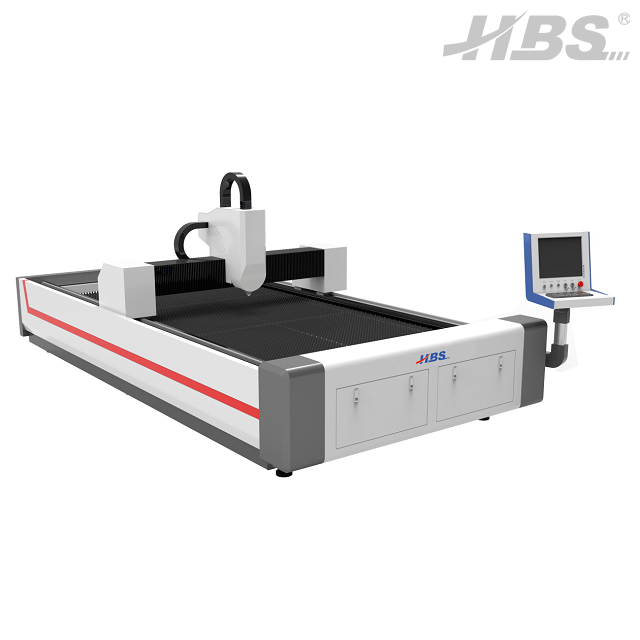
Why do these systems need specialized programs? Cutting thick carbon steel, stainless steel, or aluminum involves extreme thermal dynamics. It requires high travel speeds and the tight regulation of assist gases like Oxygen or Nitrogen. When operating a heavy-duty Fiber Laser Cutting Machine, especially advanced models like the HBS 4020 Series, the software seamlessly manages complex piercing processes. High-power systems, often ranging from 12kW to 30kW, rely on the software to execute multi-stage or progressive piercing. This allows the beam to penetrate thick metals without blowing out the protective lens. Basic control programs simply cannot process these hardware-intensive variables.
Furthermore, raw metal sheet stock is a significant manufacturing expense. Consequently, industrial software must include advanced auto-nesting capabilities. These algorithms automatically analyze, rotate, and arrange multiple parts on a single digital sheet. This maximizes material yield and minimizes scrap waste. True-shape nesting can even place smaller components inside the internal cutouts of larger parts.
To eliminate guesswork, professional platforms feature built-in, pre-tested material libraries. When an operator selects a specific material and thickness, the system automatically adjusts the pulse frequency, focal depth, cutting speed, and gas pressure. This ensures consistent cut quality across different shifts and material batches.
While flat sheet cutting operates on a standard X and Y plane, processing structural tubes and pipes introduces significant spatial complexity. This necessitates highly specialized computational workflows.
Operating a Tube Laser Cutting Machine differs fundamentally from flatbed cutters. It requires the integration of a rotary axis, such as a pneumatic chuck, to turn the material while the head moves linearly. The software must perform continuous 3D spatial calculations. This synchronizes the rotation of the tube with the movement of the cutting head, ensuring the focal distance remains perfectly constant on a curved surface.
Standard 2D software cannot handle tube geometry. Specialized programs like TubesT or Lantek are required to calculate complex intersecting cuts, weld bevels, and bend reliefs. Whether processing square, round, or elliptical tubes, the software must accurately map a 2D cut path onto a 3D rotating surface without geometric distortion.
The standard workflow for tube processing bypasses 2D DXF files entirely. Instead, engineers design the tubular structures in 3D CAD platforms and export them usually in STEP or IGES formats. The tube control software imports these 3D models, recognizes the profiles, and automatically unfolds them into machine-readable rotary toolpaths.
Regardless of whether you are operating a desktop unit or an industrial gantry, evaluating your digital tools requires a systematic approach. To make the selection process easier, refer to the core capabilities required below.
Software Category | Primary Function | Key Features to Demand | Best Used For |
|---|---|---|---|
Vector CAD | Artistic Design & 2D Layouts | Node editing, pathfinding, SVG export | Signage, acrylics, organic patterns |
Engineering CAD | Mechanical Parts & 3D Modeling | Parametric dimensions, sheet metal unfolding | Industrial brackets, enclosures, machine parts |
CAM & Control | G-code Generation & Machine Operation | Kerf compensation, auto-nesting, material libraries | Executing cuts, managing gas pressure, optimizing sheet yield |
Kerf refers to the exact physical width of the material vaporized and removed by the beam as it burns through the substrate. Because the beam has a physical thickness, typically between 0.1mm and 0.3mm, cutting directly on a design line will result in a physical part that fits loosely. Professional software includes automatic Kerf Compensation. This mathematically offsets the cutting path outward for external cuts or inward for internal holes by exactly half the beam width to maintain precise dimensional accuracy.
A versatile environment must accept various file types from different clients or design departments without data loss. Must-have import formats include DXF and DWG for mechanical parts and engineering dimensions. SVG and AI are essential for importing vector art, signage, and organic shapes from graphic designers. PDF remains a universal format for vector sharing and client proofs.
Executing a cut blindly can lead to catastrophic hardware collisions or wasted material. Simulation features allow operators to watch a sped-up, virtual run-through of the entire job on screen. This verifies the sequence of cuts, estimates the exact machining time, and ensures the head will safely clear clamps or fixtures.
Even with top-tier software, operators frequently encounter digital file anomalies that prevent successful processing. Understanding how to troubleshoot these common issues is a vital skill for any machine operator.
Open Contours and Unjoined Nodes: One of the most frequent issues is a machine refusing to cut a shape entirely out of the material. This occurs when vector lines appear connected on screen but are actually open contours, also known as unjoined nodes. The software reads them as separate line segments rather than a continuous boundary. The Fix: Utilize the close path or join nodes tool in your design software. This will automatically locate and weld broken endpoints together with a specified tolerance before exporting to the CAM system.
Redundant Double Lines: When vector lines overlap perfectly, they are often invisible to the naked eye on a computer monitor. However, the CAM software will read both lines and instruct the machine to cut the exact same path twice. This results in severe charring, excessive melting, warped metal, and potential fire hazards. The Fix: Always run the delete duplicates or remove overlapping lines command. This strips away redundant paths and ensures a single, clean pass.
Metric vs. Imperial Scaling Issues: Operators often import a DXF file only to find it is 25.4 times too small or too large. This happens due to a mismatch between metric units in millimeters and imperial units in inches during the export and import process. The Fix: Verify the unit settings in both your design and control software to ensure they align. Most control software includes a setting to explicitly define the default import unit to prevent this scaling mismatch.
Conclusion
Your journey from a digital concept to a finished, physical product relies entirely on your software stack. High-quality software transforms metal fabrication from a frustrating trial-and-error process into an easy, highly accurate manufacturing method. Hobbyists and small businesses should start by mastering basic vector tools, while industrial users must focus on engineering platforms paired with robust, machine-specific control systems.
Are you ready to upgrade your manufacturing capabilities? Pair top-tier software with world-class hardware to scale your production to new heights. Explore our advanced industrial solutions today at HBS Lasers and ensure your digital designs translate flawlessly into reality. Whether you need high-power flatbed cutters or advanced tube processing systems, we have the technology to optimize your workflow.
Frequently Asked Questions
For the design phase, Inkscape is highly recommended as it provides comprehensive vector editing tools at no cost. For machine control, LaserGRBL is the best free option, specifically optimized for operating GRBL-based desktop machines.
Yes, AutoCAD is excellent for creating highly precise dimensional designs. It exports files in DXF or DWG formats. These are the universal industry standards accepted by almost all control platforms seamlessly.
Most modern software handles both processes within the same interface. Cutting relies strictly on vector paths, which are mathematical lines, to guide the beam completely through the material. Engraving often uses raster data, or pixels, to pulse the beam. This burns images, creates shading, or fills in solid shapes on the surface.
Generally, heavy-duty industrial software like CypCut is exclusively built for Windows environments due to hardware driver requirements. However, lightweight software like LightBurn does offer full native support for Mac, making it popular for non-metal applications.
The cost varies wildly based on application. Desktop software like LightBurn ranges from $60 to $120. In contrast, industrial control systems like CypCut or advanced nesting software like SigmaNEST can range from a few thousand dollars to over $10,000, often bundled directly with the purchase of the machine.
Tube cutting requires highly specialized 3D CAM software, such as TubesT or Lantek. These programs process 3D engineering models and automatically calculate the complex rotary axis movements needed to cut cylindrical, square, or intersecting profiles accurately.

